( - if you do not like I2C do not read this blog
- it is a lot of information here which relays on your previous knowledge or the wiliness to learn more about Debian , Python and I2C )

Scope : Create an I2C controllable Robotic Arm based on
Raspberry PI hardware and cheap additional hardware - from drives to sensors.
- Short Story: Originally the project started the development using as core system a PI 2 basic hardware and integrating I2C peripherals as needed.
- I found fast that for development reasons I needed a faster and more extended hardware - so the project was migrated toward a 4 GB memory Pentium dual core system with 250 GB HDD. Thee project can be migrated back to PI without any major modifications.
- I kept the same basic operating system - by installing Debian 8 64 bits on the machine.
- The whole trick is that a regular PC platform has available sometime few I2C networks and one of them is accessible thru the VGA port.see the link (I2C adapter)
- I need to underline that the whole project is mostly a result of compiling existing information but I have to say that the I2C availability on the PC hardware really gave a bust to the development.
- Now I have to say that really the only think which you need from the site is to know that this network exists.
- The I2C is "naturally" accessible from Debian and also from R-PI.
- Not being a Linux guru , I can say the installation of Debian 8 was smooth and elegant. I works fine on Intel processors not so much on equivalent Athlon (at least Chromium doesn't like my Athlon)
- I run the system in standard user mode but by using su (super user ) command and launching the applications from a su "owned" terminal the hardware resources are easier to access.
==========================================================
It is a lot to say and explain so I will try to start by
using a general schematic of the project

Note: Probably the above image will see a lot of updates as the project description is evolving.
===========================================================
- The control hardware can by the R-Pi or a PC platform as I described above.
- The operating system for compatibility with PI and also for easiness of hardware access is the free open source Linux Debian 8 (see link: Debian - and thanks to the developers for the great work !)
===========================================================
- The development language is Python 2.7 or if you want you can migrate toward a newer version (3...). (see link:Python). Note: the IDE which I'm using is IDLE - and all this language /environment is install-able very easy from Synaptic Package Manager.
- One of the most useful application will be the Web Browser - if you need to clarify project details...(Ice weasel) search , search , search...
- So obvious some programming experience is needed here and learning Python can be a funny / frustrating experience pending from which direction are you coming .. or looking.
- Freemat ( see: Freemat ) is an excellent free (thanks !)
===========================================================
alternative to Matlab style scripts and graphic representation - it can be used for post processing data representation.

===========================================================
- GitHub (GitHub) is the main information and sources resource and the Adafriut repository(Adafruit)is essential.
- Due to the migration to PC platform for development some very basic programming sources needed minor modifications for the I2C access - mostly for pointing toward the correct I2C available network.
==========================================================
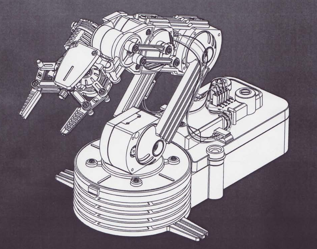
The Robot Mechanical Hardware (OWI)

Mechanical dimensions

Range of movements

Original Electrics : 6 V DC ON /OFF (not used in this project)
==========================================================
The I2C PC network from VGA:
- You can ignore the next section if you use a R-PI 2 as there the I2C is available on the 40 pin connector.(SDA , SCL)
- The VGA port has a native I2C connection available.
- The easiest way to access it is if your card has a dual port , by attaching an VGA extension cable, or eventually connecting directly in the card connector "holes". I guess this will work with an laptop by connecting to the extension VGA connector.

- The easy way to identify the pins is by looking for the 5V pin with a voltmeter. This will place you on the "map". In fact in my application I'm connecting to a DVI port with an adapter to VGA and then I'm connecting the extension cable (from an old KVM switch).
==========================================================
How to check your I2C network (Debian 8 and R-PI):
- launch terminal
- go in su mode (Debian only )
i2cdetect -l
// (to list all networks)

- if you have an I2C device attached on the network you should see it on one of the networks with
i2cdetect -y 0
//(or 1 or 2 or 3 .. usually I find 0 or 1 hosting the devices).
Note: it is possible that a computer reset or shoot down the devices will be on a different net as I learned.
The devices for which I'm looking have addresses 0X40 , 0X48 , 0X68, 0X69 , so is the I2C number 1

==========================================================
The I2C devices
which I use are already on some small boards so all signals and additional components are on the board - so is no need for the additional resistors and very rarely for 3.3 V
E-bay or Alliexpress are the main sources for the sensors and devices:
==========================================================
Electrical Hardware:
I guess with a carefully search and if you are patient with delivery time, total it can get under 50 USD except the robot itself ( around 35).
======================================================
- motor driver PWM driven good for 2 motors (using 3 boards)
Dual H Bridge Stepper Motor Drive Controller Board Module For Arduino L298N UL

 ==========================================================
- Acceleration / angular sensor :(using 4-5 of them )
MPU6050 3 Port 3-Axis Acceleration Gyroscope 6DOF Accelerometer Sensor

 ========================================================
- I2C switch (8X I2C) this board is needed to switch between sensors which has the same I2C address .
TCA9548A I2C Multiplexer Breakout board for chaining Modules
 or
or
PCA9548A 8 Channel I2C Bus Switch w/ Reset Breakout for Arduino uControllers

To access the I2C channels thru the board the next code is what I used the following PYTHON code:
********************************************************************
#!/usr/bin/python
# TCA9548A I2C multiplexer
# I2C Address: 70 through 77
# Channel: 0 - 7
#-------------------------------------------------------------------
import smbus
# class for the I2C switch------------------------------------------
class I2C_SW(object):
# init procedure
def __init__(self,name,address,bus_nr):
self.name=name
self.address=address
self.bus_nr=bus_nr
self.bus=smbus.SMBus(bus_nr)
# Change to i2c channel 0..7__________________________________________________
def chn(self,channel):
self.bus.write_byte(self.address,2**channel)
# block all channels read only the main I2c ( on which is the address SW)_____
def _rst(self):
self.bus.write_byte(self.address,0)
print self.name,' ','Switch reset'
# read all 8 channels__________________________________________________________
def _all(self):
self.bus.write_byte(self.address,0Xff)
print self.name,' ','Switch read all lines'
# define the usual sensor 0X70 bus 1
SW=I2C_SW('I2C switch 0',0X70, 1)
SW._all()
SW._rst()
# to enable a channel : SW_chn(channel number - here 0 to 7)
# check with i2cdetect y -1 (if bus_nr=1)
PCA9685 16-Channel 12-bit PWM Servo motor Driver I2C Module


The robot fully wired .- not pretty yet...

Back to robot philosophy
========================

- The basic accomplishment should be to be able to use an USB joy-pad to proportionally drive the electric motors Mxx with the displacement of the 2 X 2 axis joystick in the pad.
The association between the joystick movements and the motor movements are presented in the above picture.
- Further a more elaborate accomplishment is to associate the movements of the joysticks with a X/Y 2D space in the plan of the robot arm.
- In fact the whole construction is targeting the scope of being able to move the gripper in a controlled manner in an X/Y coordinate system with the origin in the rotational axis of the arm and ground.
- This control can be moved easy in 3D by extending the coordinate system to a cylindrical one (R,Ro,Fi).
The final hardware setting looks as (the cat is only wondering..) :

==========================================================
Basic control system - first look:
There are few layers of work and theory to dig into but the simplest approach is :
Let connect the electric motors from the robot with the joy-pad sticks.
There are 5 basic movements:

On Left Stick:
==============
- Swing (Base rotation) M5 - Left Stick left to right
- Stick (or Elbow motion) M3 Lfet Stick back (up) or forward (down)
On Right Stick:
===============
- Wrist - M2 - Right stick left ( Wrist Up) to right (Wrist down)
- Boom (Hoist) - (Base ) M4 Right stick forward (down) or back (up)
On Left and Right Buttons
=========================
- Gripper-M1 open (Left) and Close (Right)
==========================================================
To get a proportional association between the speed of the electric 6V DC motor( M1..M5) and the joystick displacement we need to :
- Read The Joystick
- Decide the correlation between Joystick reading and the speed and sense of motor shaft rotation (command signal - PWM signal)
- Transform the command signal to electric power to be sent to the electric DC motor using an amplifier or a "driver ' which in this case should be a bridge ( allows reversing the shaft rotation direction.
Note: the trigonometric convention for angles sign is used here also, this means that looking from the shaft end the rotation sense is positive if goes counter clock wise ( CCW=+)
Let eat the elephant slowly:
============================
initial assumption :
- the Debian (or Raspberry PI) operating system is installed, Python 2.7 is installed and you are able to start the IDE with "idle"
- You should be in Root mode or engage SU from a terminal window followed by "idle".
I found that the simplest way to read the USB joystick is by reading it thru the Python package called PYGAME (http://www.pygame.org/docs/ref/joystick.html)

You can install Pygame from package manager directly.
If you will connect your USB pad to the computer USB port the pygame should be able to read the joystick(s) and buttons.
GitHub has a package for it and is a good one because let you to identify the names of the stick and buttons in a graphical screen. The bases for the readings from the joy-pad are coming from this program.
Here is the basic program output:

You can have more than 1 USB joystick and will identify. it correctly. When you press the buttons or move the sticks the values are changing.
For the sticks the values are -1 to 1 on 10 bit ( if I remember correctly)
Here is the basic program (credit to... ) :
**********************************************************
import pygame
# Define omse colors
BLACK = ( 0, 0, 0)
WHITE = ( 255, 255, 255)
# This is a simple class that will help us print to the screen
# It has nothing to do with the joysticks, just outputing the
# information.
class TextPrint:
def __init__(self):
self.reset()
self.font = pygame.font.Font(None, 20)
def print_(self, screen, textString):
textBitmap = self.font.render(textString, True, BLACK)
screen.blit(textBitmap, [self.x, self.y])
self.y += self.line_height
def reset(self):
self.x = 10
self.y = 10
self.line_height = 15
def indent(self):
self.x += 10
def unindent(self):
self.x -= 10
pygame.init()
# Set the width and height of the screen [width,height]
size = [500, 700]
screen = pygame.display.set_mode(size)
pygame.display.set_caption("My Game")
#Loop until the user clicks the close button.
done = False
# Used to manage how fast the screen updates
clock = pygame.time.Clock()
# Initialize the joysticks
pygame.joystick.init()
# Get ready to print
textPrint = TextPrint()
# -------- Main Program Loop -----------
while done==False:
# EVENT PROCESSING STEP
for event in pygame.event.get(): # User did something
if event.type == pygame.QUIT: # If user clicked close
done=True # Flag that we are done so we exit this loop
# Possible joystick actions: JOYAXISMOTION JOYBALLMOTION JOYBUTTONDOWN JOYBUTTONUP JOYHATMOTION
if event.type == pygame.JOYBUTTONDOWN:
print("Joystick button pressed.")
if event.type == pygame.JOYBUTTONUP:
print("Joystick button released.")
# DRAWING STEP
# First, clear the screen to white. Don't put other drawing commands
# above this, or they will be erased with this command.
screen.fill(WHITE)
textPrint.reset()
# Get count of joysticks
joystick_count = pygame.joystick.get_count()
textPrint.print_(screen, "Number of joysticks: {}".format(joystick_count) )
textPrint.indent()
# For each joystick:
for i in range(joystick_count):
joystick = pygame.joystick.Joystick(i)
joystick.init()
textPrint.print_(screen, "Joystick {}".format(i) )
textPrint.indent()
# Get the name from the OS for the controller/joystick
name = joystick.get_name()
textPrint.print_(screen, "Joystick name: {}".format(name) )
# Usually axis run in pairs, up/down for one, and left/right for
# the other.
axes = joystick.get_numaxes()
textPrint.print_(screen, "Number of axes: {}".format(axes) )
textPrint.indent()
for i in range( axes ):
axis = joystick.get_axis( i )
textPrint.print_(screen, "Axis {} value: {:>6.3f}".format(i, axis) )
textPrint.unindent()
buttons = joystick.get_numbuttons()
textPrint.print_(screen, "Number of buttons: {}".format(buttons) )
textPrint.indent()
for i in range( buttons ):
button = joystick.get_button( i )
textPrint.print_(screen, "Button {:>2} value: {}".format(i,button) )
textPrint.unindent()
# Hat switch. All or nothing for direction, not like joysticks.
# Value comes back in an array.
hats = joystick.get_numhats()
textPrint.print_(screen, "Number of hats: {}".format(hats) )
textPrint.indent()
for i in range( hats ):
hat = joystick.get_hat( i )
textPrint.print_(screen, "Hat {} value: {}".format(i, str(hat)) )
textPrint.unindent()
textPrint.unindent()
# ALL CODE TO DRAW SHOULD GO ABOVE THIS COMMENT
# Go ahead and update the screen with what we've drawn.
pygame.display.flip()
# Limit to 20 frames per second
clock.tick(20)
# Close the window and quit.
# If you forget this line, the program will 'hang'
# on exit if running from IDLE.
pygame.quit ()
*********************************************************
A much reduced version for sticks only looks like:
**********************************************************
import pygame
from time import *
pygame.init()
pygame.joystick.init()
joystick_count = pygame.joystick.get_count()
print("Number of joysticks: {}".format(joystick_count) )
for i in range(joystick_count):
joystick = pygame.joystick.Joystick(i)
joystick.init()
print("Joystick {}".format(i) )
# Get the name from the OS for the controller/joystick
name = joystick.get_name()
print( "Joystick name: {}".format(name) )
axes = joystick.get_numaxes()
print("Number of axes: {}".format(axes) )
while True:
joystick = pygame.joystick.Joystick(0)
#sleep(0.01)
pygame.event.pump()
for i in range( 4 ):
axis = joystick.get_axis( i )
print "%3d"%i,'='," %9.3f" % axis,' ',
print
joystick = pygame.joystick.Joystick(0)
#sleep(0.01)
pygame.event.pump()
for i in range( 4 ):
axis = joystick.get_axis( i )
print "%3d"%i,'='," %9.3f" % axis,' ',
print
For PWM explanation try :
https://en.wikipedia.org/wiki/Pulse-width_modulation
The PWM device which we will use is a I2C - PWM controller which is able to run 0-15 PWM different signals out with the same basic frequency.
I used :
PCA9685 16-Channel 12-bit PWM Servo motor Driver I2C Module board

Short description :
The twitch in the application of this controller is that the motors which we will use are purely DC motors and NOT servo drives.
For this application in fact the forward / reverse / stop of the motor is done by the differential voltage between 2 PWM outputs.
So for example to drive the motor 'X' we need to connect the amplifier to PWM0 And PWM1 (yellow connector pins) and ignore the Voltage and Ground pins.
The next is that this controller is driven thru the I2C protocol, so now we should have a better look nto the application of the I2C protocol.
The basics are explained here:
https://en.wikipedia.org/wiki/I%C2%B2C
or
https://learn.sparkfun.com/tutorials/i2c
and they look ... complex.
Fortunately the whole internet is full with applications using Python and I2C protocols.
Really what you ned to be sure is that :
1. Your system has the I2C enabled (the I2Cdetect is reporting the network)
2. Your I2C device is correctly connected to network.
If you are using Raspberry PI "no 1" is easy to handle by using the configuration menu . For a regular Debian the mdprobe has to be used and usualy you have tto be in su mode.
Connect the controller to +5V , GND SLC and SDA of the network.

the -l parameter is listing all networks and -y 1 (or 0..0 is listing devices on the particular net.
In the above picture I have other devices on the net but the address 0X70 and 0X40 show that our PWM controller is online.
The board connected is in the next picture.

Some connection details:(VCC 5V, SDA,SLC,GND),no higher than 5V is needed here.


I2C access basics
There are few basic program sources under Pyton what we need to load to access the PWM PCA9685 16-Channel 12-bit PWM Servo motor Driver I2C Module board controller:
The first collection of procedures is called smbus.
You can install python - smbus package from pakage manager n( run a search on smbus).
If the installation was succesful then from idle you can request :
import smbus
help('smbus')
and a list of procedures and functions should be on the screen.
>>> help('smbus')
Help on module smbus:
==========================================================
NAME
smbus
FILE
/usr/lib/python2.7/dist-packages/smbus.so
DESCRIPTION
This module defines an object type that allows SMBus transactions
on hosts running the Linux kernel. The host kernel must have I2C
support, I2C device interface support, and a bus adapter driver.
All of these can be either built-in to the kernel, or loaded from
modules.
Because the I2C device interface is opened R/W, users of this
module usually must have root permissions.
=========================================================
The I2C access package is based on Adafruit public source code which i modified to fit to the multiple networks of my Debian system.
CNN / IMG identification approach :

General Schematic:

Note: Probably the above image will see a lot of updates as the project description is evolving.
===========================================================
- The control hardware can by the R-Pi or a PC platform as I described above.
- The operating system for compatibility with PI and also for easiness of hardware access is the free open source Linux Debian 8 (see link: Debian - and thanks to the developers for the great work !)
===========================================================
- The development language is Python 2.7 or if you want you can migrate toward a newer version (3...). (see link:Python). Note: the IDE which I'm using is IDLE - and all this language /environment is install-able very easy from Synaptic Package Manager.
- One of the most useful application will be the Web Browser - if you need to clarify project details...(Ice weasel) search , search , search...
- So obvious some programming experience is needed here and learning Python can be a funny / frustrating experience pending from which direction are you coming .. or looking.
- Freemat ( see: Freemat ) is an excellent free (thanks !)
===========================================================
alternative to Matlab style scripts and graphic representation - it can be used for post processing data representation.

===========================================================
- GitHub (GitHub) is the main information and sources resource and the Adafriut repository(Adafruit)is essential.
- Due to the migration to PC platform for development some very basic programming sources needed minor modifications for the I2C access - mostly for pointing toward the correct I2C available network.
==========================================================
The Robot Mechanical Hardware (OWI)

Mechanical dimensions

Range of movements

Original Electrics : 6 V DC ON /OFF (not used in this project)
==========================================================
The I2C PC network from VGA:
- You can ignore the next section if you use a R-PI 2 as there the I2C is available on the 40 pin connector.(SDA , SCL)
- The VGA port has a native I2C connection available.
- The easiest way to access it is if your card has a dual port , by attaching an VGA extension cable, or eventually connecting directly in the card connector "holes". I guess this will work with an laptop by connecting to the extension VGA connector.
- The easy way to identify the pins is by looking for the 5V pin with a voltmeter. This will place you on the "map". In fact in my application I'm connecting to a DVI port with an adapter to VGA and then I'm connecting the extension cable (from an old KVM switch).
==========================================================
How to check your I2C network (Debian 8 and R-PI):
- launch terminal
- go in su mode (Debian only )
i2cdetect -l
// (to list all networks)

- if you have an I2C device attached on the network you should see it on one of the networks with
i2cdetect -y 0
//(or 1 or 2 or 3 .. usually I find 0 or 1 hosting the devices).
Note: it is possible that a computer reset or shoot down the devices will be on a different net as I learned.
The devices for which I'm looking have addresses 0X40 , 0X48 , 0X68, 0X69 , so is the I2C number 1

==========================================================
The I2C devices
which I use are already on some small boards so all signals and additional components are on the board - so is no need for the additional resistors and very rarely for 3.3 V
E-bay or Alliexpress are the main sources for the sensors and devices:
==========================================================
Electrical Hardware:
I guess with a carefully search and if you are patient with delivery time, total it can get under 50 USD except the robot itself ( around 35).
======================================================
- motor driver PWM driven good for 2 motors (using 3 boards)
Dual H Bridge Stepper Motor Drive Controller Board Module For Arduino L298N UL

==========================================================
- 16 bit AD 4 channel AD converter
16 Bit I2C 4 channel ADS1115 Module ADC with Pro Gain Amplifier for Arduino

- Acceleration / angular sensor :(using 4-5 of them )
MPU6050 3 Port 3-Axis Acceleration Gyroscope 6DOF Accelerometer Sensor

==========================================================
-Connecting wires:40pcs Dupont 20CM Male To Male Jumper Wire Ribbon Cable Breadboard

- I2C switch (8X I2C) this board is needed to switch between sensors which has the same I2C address .
TCA9548A I2C Multiplexer Breakout board for chaining Modules

PCA9548A 8 Channel I2C Bus Switch w/ Reset Breakout for Arduino uControllers

To access the I2C channels thru the board the next code is what I used the following PYTHON code:
********************************************************************
#!/usr/bin/python
# TCA9548A I2C multiplexer
# I2C Address: 70 through 77
# Channel: 0 - 7
#-------------------------------------------------------------------
import smbus
# class for the I2C switch------------------------------------------
class I2C_SW(object):
# init procedure
def __init__(self,name,address,bus_nr):
self.name=name
self.address=address
self.bus_nr=bus_nr
self.bus=smbus.SMBus(bus_nr)
# Change to i2c channel 0..7__________________________________________________
def chn(self,channel):
self.bus.write_byte(self.address,2**channel)
# block all channels read only the main I2c ( on which is the address SW)_____
def _rst(self):
self.bus.write_byte(self.address,0)
print self.name,' ','Switch reset'
# read all 8 channels__________________________________________________________
def _all(self):
self.bus.write_byte(self.address,0Xff)
print self.name,' ','Switch read all lines'
# define the usual sensor 0X70 bus 1
SW=I2C_SW('I2C switch 0',0X70, 1)
SW._all()
SW._rst()
# to enable a channel : SW_chn(channel number - here 0 to 7)
# check with i2cdetect y -1 (if bus_nr=1)
*********************************************************
Because the PWM driver (next component) is broadcasting 0X70 and 0X40 the I2C Switch adress is changed by hardware to 0X74.
 Which means to short solder 2 small pads on the board:

and in above code address 0x74 must be used not 0x70
==========================================================
- I2C PWM generator - this is essential for your drivers command


and in above code address 0x74 must be used not 0x70
==========================================================
- I2C PWM generator - this is essential for your drivers command
PCA9685 16-Channel 12-bit PWM Servo motor Driver I2C Module

==========================================================
- Analog 16 Channel mixer
CD74HC4067 CMOS 16 CH Analog Digital MUX Breakout Board

=========================================================
- USB Joystick (Joypad) - connected to the USB port

==========================================================
For all I2C devices basic Python application can be found on GitHub or instructions on Instructables, or R-PI associated sources.
I will fully share all Python sources in this post later.

Back to robot philosophy
========================

The association between the joystick movements and the motor movements are presented in the above picture.
- Further a more elaborate accomplishment is to associate the movements of the joysticks with a X/Y 2D space in the plan of the robot arm.
- In fact the whole construction is targeting the scope of being able to move the gripper in a controlled manner in an X/Y coordinate system with the origin in the rotational axis of the arm and ground.
- This control can be moved easy in 3D by extending the coordinate system to a cylindrical one (R,Ro,Fi).
The final hardware setting looks as (the cat is only wondering..) :

==========================================================
Basic control system - first look:
There are few layers of work and theory to dig into but the simplest approach is :
Let connect the electric motors from the robot with the joy-pad sticks.
There are 5 basic movements:

On Left Stick:
==============
- Swing (Base rotation) M5 - Left Stick left to right
- Stick (or Elbow motion) M3 Lfet Stick back (up) or forward (down)
On Right Stick:
===============
- Wrist - M2 - Right stick left ( Wrist Up) to right (Wrist down)
- Boom (Hoist) - (Base ) M4 Right stick forward (down) or back (up)
On Left and Right Buttons
=========================
- Gripper-M1 open (Left) and Close (Right)
==========================================================
To get a proportional association between the speed of the electric 6V DC motor( M1..M5) and the joystick displacement we need to :
- Read The Joystick
- Decide the correlation between Joystick reading and the speed and sense of motor shaft rotation (command signal - PWM signal)
- Transform the command signal to electric power to be sent to the electric DC motor using an amplifier or a "driver ' which in this case should be a bridge ( allows reversing the shaft rotation direction.
Note: the trigonometric convention for angles sign is used here also, this means that looking from the shaft end the rotation sense is positive if goes counter clock wise ( CCW=+)
Let eat the elephant slowly:
============================
initial assumption :
- the Debian (or Raspberry PI) operating system is installed, Python 2.7 is installed and you are able to start the IDE with "idle"
- You should be in Root mode or engage SU from a terminal window followed by "idle".
I found that the simplest way to read the USB joystick is by reading it thru the Python package called PYGAME (http://www.pygame.org/docs/ref/joystick.html)

You can install Pygame from package manager directly.
If you will connect your USB pad to the computer USB port the pygame should be able to read the joystick(s) and buttons.
GitHub has a package for it and is a good one because let you to identify the names of the stick and buttons in a graphical screen. The bases for the readings from the joy-pad are coming from this program.
Here is the basic program output:

You can have more than 1 USB joystick and will identify. it correctly. When you press the buttons or move the sticks the values are changing.
For the sticks the values are -1 to 1 on 10 bit ( if I remember correctly)
Here is the basic program (credit to... ) :
**********************************************************
import pygame
# Define omse colors
BLACK = ( 0, 0, 0)
WHITE = ( 255, 255, 255)
# This is a simple class that will help us print to the screen
# It has nothing to do with the joysticks, just outputing the
# information.
class TextPrint:
def __init__(self):
self.reset()
self.font = pygame.font.Font(None, 20)
def print_(self, screen, textString):
textBitmap = self.font.render(textString, True, BLACK)
screen.blit(textBitmap, [self.x, self.y])
self.y += self.line_height
def reset(self):
self.x = 10
self.y = 10
self.line_height = 15
def indent(self):
self.x += 10
def unindent(self):
self.x -= 10
pygame.init()
# Set the width and height of the screen [width,height]
size = [500, 700]
screen = pygame.display.set_mode(size)
pygame.display.set_caption("My Game")
#Loop until the user clicks the close button.
done = False
# Used to manage how fast the screen updates
clock = pygame.time.Clock()
# Initialize the joysticks
pygame.joystick.init()
# Get ready to print
textPrint = TextPrint()
# -------- Main Program Loop -----------
while done==False:
# EVENT PROCESSING STEP
for event in pygame.event.get(): # User did something
if event.type == pygame.QUIT: # If user clicked close
done=True # Flag that we are done so we exit this loop
# Possible joystick actions: JOYAXISMOTION JOYBALLMOTION JOYBUTTONDOWN JOYBUTTONUP JOYHATMOTION
if event.type == pygame.JOYBUTTONDOWN:
print("Joystick button pressed.")
if event.type == pygame.JOYBUTTONUP:
print("Joystick button released.")
# DRAWING STEP
# First, clear the screen to white. Don't put other drawing commands
# above this, or they will be erased with this command.
screen.fill(WHITE)
textPrint.reset()
# Get count of joysticks
joystick_count = pygame.joystick.get_count()
textPrint.print_(screen, "Number of joysticks: {}".format(joystick_count) )
textPrint.indent()
# For each joystick:
for i in range(joystick_count):
joystick = pygame.joystick.Joystick(i)
joystick.init()
textPrint.print_(screen, "Joystick {}".format(i) )
textPrint.indent()
# Get the name from the OS for the controller/joystick
name = joystick.get_name()
textPrint.print_(screen, "Joystick name: {}".format(name) )
# Usually axis run in pairs, up/down for one, and left/right for
# the other.
axes = joystick.get_numaxes()
textPrint.print_(screen, "Number of axes: {}".format(axes) )
textPrint.indent()
for i in range( axes ):
axis = joystick.get_axis( i )
textPrint.print_(screen, "Axis {} value: {:>6.3f}".format(i, axis) )
textPrint.unindent()
buttons = joystick.get_numbuttons()
textPrint.print_(screen, "Number of buttons: {}".format(buttons) )
textPrint.indent()
for i in range( buttons ):
button = joystick.get_button( i )
textPrint.print_(screen, "Button {:>2} value: {}".format(i,button) )
textPrint.unindent()
# Hat switch. All or nothing for direction, not like joysticks.
# Value comes back in an array.
hats = joystick.get_numhats()
textPrint.print_(screen, "Number of hats: {}".format(hats) )
textPrint.indent()
for i in range( hats ):
hat = joystick.get_hat( i )
textPrint.print_(screen, "Hat {} value: {}".format(i, str(hat)) )
textPrint.unindent()
textPrint.unindent()
# ALL CODE TO DRAW SHOULD GO ABOVE THIS COMMENT
# Go ahead and update the screen with what we've drawn.
pygame.display.flip()
# Limit to 20 frames per second
clock.tick(20)
# Close the window and quit.
# If you forget this line, the program will 'hang'
# on exit if running from IDLE.
pygame.quit ()
A much reduced version for sticks only looks like:
**********************************************************
import pygame
from time import *
pygame.init()
pygame.joystick.init()
joystick_count = pygame.joystick.get_count()
print("Number of joysticks: {}".format(joystick_count) )
for i in range(joystick_count):
joystick = pygame.joystick.Joystick(i)
joystick.init()
print("Joystick {}".format(i) )
# Get the name from the OS for the controller/joystick
name = joystick.get_name()
print( "Joystick name: {}".format(name) )
axes = joystick.get_numaxes()
print("Number of axes: {}".format(axes) )
while True:
joystick = pygame.joystick.Joystick(0)
#sleep(0.01)
pygame.event.pump()
for i in range( 4 ):
axis = joystick.get_axis( i )
print "%3d"%i,'='," %9.3f" % axis,' ',
joystick = pygame.joystick.Joystick(0)
#sleep(0.01)
pygame.event.pump()
for i in range( 4 ):
axis = joystick.get_axis( i )
print "%3d"%i,'='," %9.3f" % axis,' ',
**********************************************************
The next step is a litle mode complex and needs to generate the PWM signal for the DC motor associated with the joystick output.For PWM explanation try :
https://en.wikipedia.org/wiki/Pulse-width_modulation
The PWM device which we will use is a I2C - PWM controller which is able to run 0-15 PWM different signals out with the same basic frequency.
I used :
PCA9685 16-Channel 12-bit PWM Servo motor Driver I2C Module board

Short description :
Using
only two pins, control 16 free-running PWM outputs!
You can even chain up 62 breakouts to control up to 992 PWM outputs
You can even chain up 62 breakouts to control up to 992 PWM outputs
It's
an i2c-controlled PWM driver with a built in clock. That means that, unlike the
TLC5940 family, you do not need to continuously send it signal tying up your
microcontroller, its completely free running!
It is
5V compliant, which means you can control it from a 3.3V microcontroller and
still safely drive up to 6V outputs (this is good for when you want to control
white or blue LEDs with 3.4+ forward voltages)
6
address select pins so you can wire up to 62 of these on a single i2c bus, a
total of 992 outputs - that's a lot of servos or LEDs
Adjustable
frequency PWM up to about 1.6 KHz
12-bit
resolution for each output - for servos, that means about 4us resolution at
60Hz update rate
Configurable
push-pull or open-drain output
Output
enable pin to quickly disable all the outputs
Wrapped up this lovely chip into a breakout board with a couple nice extras
Terminal
block for power input (or you can use the 0.1" breakouts on the side)
Reverse
polarity protection on the terminal block input
Green
power-good LED
3 pin
connectors in groups of 4 so you can plug in 16 servos at once (Servo plugs are
slightly wider than 0.1" so you can only stack 4 next to each other on
0.1" header
"Chain-able" design
A
spot to place a big capacitor on the V+ line (in case you need it)
330
ohm series resistors on all the output lines to protect them, and to make
driving LEDs trivial
Solder
jumpers for the 6 address select pinsThe twitch in the application of this controller is that the motors which we will use are purely DC motors and NOT servo drives.
For this application in fact the forward / reverse / stop of the motor is done by the differential voltage between 2 PWM outputs.
So for example to drive the motor 'X' we need to connect the amplifier to PWM0 And PWM1 (yellow connector pins) and ignore the Voltage and Ground pins.
The next is that this controller is driven thru the I2C protocol, so now we should have a better look nto the application of the I2C protocol.
The basics are explained here:
https://en.wikipedia.org/wiki/I%C2%B2C
or
https://learn.sparkfun.com/tutorials/i2c
and they look ... complex.
Fortunately the whole internet is full with applications using Python and I2C protocols.
Really what you ned to be sure is that :
1. Your system has the I2C enabled (the I2Cdetect is reporting the network)
2. Your I2C device is correctly connected to network.
If you are using Raspberry PI "no 1" is easy to handle by using the configuration menu . For a regular Debian the mdprobe has to be used and usualy you have tto be in su mode.
Connect the controller to +5V , GND SLC and SDA of the network.

the -l parameter is listing all networks and -y 1 (or 0..0 is listing devices on the particular net.
In the above picture I have other devices on the net but the address 0X70 and 0X40 show that our PWM controller is online.
The board connected is in the next picture.

Some connection details:(VCC 5V, SDA,SLC,GND),no higher than 5V is needed here.


I2C access basics
There are few basic program sources under Pyton what we need to load to access the PWM PCA9685 16-Channel 12-bit PWM Servo motor Driver I2C Module board controller:
The first collection of procedures is called smbus.
You can install python - smbus package from pakage manager n( run a search on smbus).
If the installation was succesful then from idle you can request :
import smbus
help('smbus')
and a list of procedures and functions should be on the screen.
>>> help('smbus')
Help on module smbus:
==========================================================
NAME
smbus
FILE
/usr/lib/python2.7/dist-packages/smbus.so
DESCRIPTION
This module defines an object type that allows SMBus transactions
on hosts running the Linux kernel. The host kernel must have I2C
support, I2C device interface support, and a bus adapter driver.
All of these can be either built-in to the kernel, or loaded from
modules.
Because the I2C device interface is opened R/W, users of this
module usually must have root permissions.
=========================================================
The I2C access package is based on Adafruit public source code which i modified to fit to the multiple networks of my Debian system.
CNN / IMG identification approach :

Hello, Mr. Robototic! Good Job!
ReplyDelete