Note: Probably the above image will see a lot of updates as the project description is evolving.
===========================================================
-
The control hardware can by the R-Pi or a PC platform as I described above.
- The operating system for compatibility with PI and also for easiness of hardware access is the free open source Linux Debian 8 (see link:
Debian - and thanks to the developers for the great work !)
===========================================================
-
The development language is Python 2.7 or if you want you can migrate toward a newer version (3...). (see link:
Python). Note: the IDE which I'm using is IDLE - and all this language /environment is install-able very easy from Synaptic Package Manager.
- One of the most useful application will be the Web Browser - if you need to clarify project details...(Ice weasel) search , search , search...
- So obvious some programming experience is needed here and learning Python can be a funny / frustrating experience pending from which direction are you coming .. or looking.
-
Freemat ( see:
Freemat ) is an excellent free (thanks !)
===========================================================
alternative to Matlab style scripts and graphic representation - it can be used for post processing data representation.
===========================================================
-
GitHub (
GitHub) is the main information and sources resource and the
Adafriut repository(
Adafruit)is essential.
- Due to the migration to PC platform for development some very basic programming sources needed minor modifications for the I2C access - mostly for pointing toward the correct I2C available network.
==========================================================
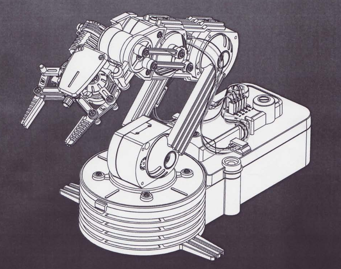
The Robot Mechanical Hardware (
OWI)
Mechanical dimensions
Range of movements
Original Electrics : 6 V DC ON /OFF (not used in this project)
==========================================================
The I2C PC network from VGA:
- You can ignore the next section if you use a R-PI 2 as there the I2C is available on the 40 pin connector.(SDA , SCL)
- The VGA port has a native I2C connection available.
- The easiest way to access it is if your card has a dual port , by attaching an VGA extension cable, or eventually connecting directly in the card connector "holes". I guess this will work with an laptop by connecting to the extension VGA connector.
- The easy way to identify the pins is by looking for the 5V pin with a voltmeter. This will place you on the "map". In fact in my application I'm connecting to a DVI port with an adapter to VGA and then I'm connecting the extension cable (from an old KVM switch).
==========================================================
How to check your I2C network (Debian 8 and R-PI):
- launch terminal
- go in su mode (Debian only )
i2cdetect -l
// (to list all networks)
- if you have an I2C device attached on the network you should see it on one of the networks with
i2cdetect -y 0
//(or 1 or 2 or 3 .. usually I find 0 or 1 hosting the devices).
Note: it is possible that a computer reset or shoot down the devices will be on a different net as I learned.
The devices for which I'm looking have addresses 0X40 , 0X48 , 0X68, 0X69 , so is the I2C number 1
==========================================================
The I2C devices
which I use are already on some small boards so all signals and additional components are on the board - so is no need for the additional resistors and very rarely for 3.3 V
E-bay or Alliexpress are the main sources for the sensors and devices:
==========================================================
Electrical Hardware:
I guess with a carefully search and if you are patient with delivery time, total it can get under 50 USD except the robot itself ( around 35).
======================================================
-
motor driver PWM driven good for 2 motors (using 3 boards)
Dual H Bridge Stepper Motor Drive Controller Board Module For Arduino L298N UL
==========================================================
- 16 bit AD 4 channel AD converter
16 Bit I2C 4 channel ADS1115 Module ADC with Pro Gain Amplifier for Arduino
==========================================================
-
Acceleration / angular sensor :(using 4-5 of them )
MPU6050 3 Port 3-Axis Acceleration Gyroscope 6DOF Accelerometer Sensor
==========================================================
-Connecting wires:
40pcs Dupont 20CM Male To Male Jumper Wire Ribbon Cable Breadboard
========================================================
- I2C switch (8X I2C) this board is needed to switch between sensors which has the same I2C address .
TCA9548A I2C Multiplexer Breakout board for chaining Modules
or
PCA9548A 8 Channel I2C Bus Switch w/ Reset Breakout for Arduino uControllers
To access the I2C channels thru the board the next code is what I used the following PYTHON code:
********************************************************************
#!/usr/bin/python
# TCA9548A I2C multiplexer
# I2C Address: 70 through 77
# Channel: 0 - 7
#-------------------------------------------------------------------
import smbus
# class for the I2C switch------------------------------------------
class I2C_SW(object):
# init procedure
def __init__(self,name,address,bus_nr):
self.name=name
self.address=address
self.bus_nr=bus_nr
self.bus=smbus.SMBus(bus_nr)
# Change to i2c channel 0..7__________________________________________________
def chn(self,channel):
self.bus.write_byte(self.address,2**channel)
# block all channels read only the main I2c ( on which is the address SW)_____
def _rst(self):
self.bus.write_byte(self.address,0)
print self.name,' ','Switch reset'
# read all 8 channels__________________________________________________________
def _all(self):
self.bus.write_byte(self.address,0Xff)
print self.name,' ','Switch read all lines'
# define the usual sensor 0X70 bus 1
SW=I2C_SW('I2C switch 0',0X70, 1)
SW._all()
SW._rst()
# to enable a channel : SW_chn(channel number - here 0 to 7)
# check with i2cdetect y -1 (if bus_nr=1)
*********************************************************
Because the PWM driver (next component) is broadcasting 0X70 and 0X40 the I2C Switch adress is changed by hardware to 0X74.
Which means to short solder 2 small pads on the board:
and in above code address 0x74 must be used not 0x70
==========================================================
- I2C PWM generator - this is essential for your drivers command
==========================================================
- Analog 16 Channel mixer
CD74HC4067 CMOS 16 CH Analog Digital MUX Breakout Board
=========================================================
- USB Joystick (Joypad) - connected to the USB port
==========================================================
For all I2C devices basic Python application can be found on GitHub or instructions on
Instructables, or R-PI associated sources.
I will fully share all Python sources in this post later.
The robot fully wired .- not pretty yet...
Back to robot philosophy
========================
- The basic accomplishment should be to be able to use an USB joy-pad to proportionally drive the electric motors Mxx with the displacement of the 2 X 2 axis joystick in the pad.
The association between the joystick movements and the motor movements are presented in the above picture.
- Further a more elaborate accomplishment is to associate the movements of the joysticks with a X/Y 2D space in the plan of the robot arm.
- In fact the whole construction is targeting the scope of being able to move the gripper in a controlled manner in an X/Y coordinate system with the origin in the rotational axis of the arm and ground.
- This control can be moved easy in 3D by extending the coordinate system to a cylindrical one (R,Ro,Fi).
The final hardware setting looks as (the cat is only wondering..) :


 This is what the camera would see eventually:
 And images taken in different points (and arms angles) look something as :